

Dynamic Armature Grid
From Diagonals to Compositional Axes
Some compositional guides are remarkably simple: a central axis, a pair of diagonals, or a few key intersections. At other times, artists may benefit from examining a richer network of relationships across the picture plane. The Dynamic Armature Grid combines diagonal directions, lines perpendicular to those diagonals, and vertical and horizontal axes passing through selected intersections.
It is a tool for analysis rather than a set of placement rules. Its purpose is not to supply as many positions for objects as possible. More important is its ability to reveal relationships between large shapes, intervals, movement, and potential areas of emphasis.
What Makes Up the Grid?
The Dynamic Armature Grid used in REGIS ARS builds on the Harmonic Armature discussed in the preceding MATRIVIO article. First, two diagonals connect opposite corners of the rectangle. From each corner, another line is drawn perpendicular to the main diagonal that does not pass through that corner. These four perpendicular lines are extended until they meet the canvas boundaries.
Next, two perpendicular-foot points on the diagonal running from the upper-left to the lower-right corner are used to construct full-height vertical lines and full-width horizontal lines. This adds four axes to the initial construction.
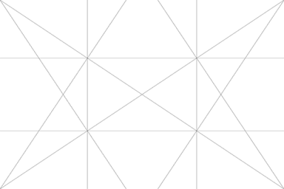
For a nonsquare format, ARS generates ten line objects: two main diagonals, four perpendicular lines, two verticals, and two horizontals. The outer canvas boundary is not counted. This precisely defined implementation should not be assumed to be identical to every other diagram described as a dynamic symmetry or armature grid.
Why Do the Added Axes Fall Where They Do?
Let the picture width be W and its height be H, with coordinates measured from the upper-left corner. Set D = W² + H². The perpendicular-foot points on the primary diagonal are obtained by projecting the upper-right and lower-left corners onto that diagonal.
The first point has coordinates (W³/D, H·W²/D), while the second is (W·H²/D, H³/D). Define a = W²/D and b = H²/D, so that a + b = 1. The two vertical grid lines lie at x = aW and x = bW; the horizontal lines lie at y = aH and y = bH.
The additional axes therefore come in symmetric pairs, but their actual positions depend on the aspect ratio of the picture. They do not represent a universal rule-of-thirds grid or a mandatory golden-ratio division. Changing the canvas proportions changes the construction.
Example: A 60 × 40 cm Canvas
Here W² = 3600, H² = 1600, and D = 5200. Therefore a = 9/13 ≈ 0.6923 and b = 4/13 ≈ 0.3077.
- Vertical lines: x ≈ 18.46 cm and x ≈ 41.54 cm.
- Horizontal lines: y ≈ 12.31 cm and y ≈ 27.69 cm.
- Feet of the perpendiculars on one main diagonal: (41.54, 27.69) and (18.46, 12.31) cm.
By comparison, an ordinary rule-of-thirds grid would place its verticals at 20 and 40 cm and its horizontals at approximately 13.33 and 26.67 cm. The difference is modest but mathematically real. A useful special case occurs when the ratio of the longer to the shorter side is √2: the additional axes then coincide with the one-third and two-third divisions.
On a square canvas, the two calculated positions coincide at the centre. ARS omits the duplicated second vertical and horizontal axes. The perpendicular lines also coincide with the main diagonals, so the visible result is essentially an X combined with a central horizontal and vertical cross.

What Can the Lines Tell an Artist?
Directional relationships. The diagonals help reveal the orientation of elongated shapes, shadow boundaries, or implied movement. Vertical and horizontal axes make it easier to compare these with steadier elements, such as a horizon, architectural features, or the surface supporting a still life.
Relationships between groups. Instead of placing every object on an intersection, an artist can establish one principal group and examine the relationship of a secondary group to it. The intervals between forms may prove more important than their alignment with geometric points.
Scale and rhythm. The added axes make subdivisions easier to examine, helping the artist recognize repeated edges, pauses, and areas of unequal width. The grid does not, however, create rhythm by itself. Rhythm emerges from the actual painted forms and their relationships.
Practical Applications
For still life, the grid is especially useful during initial thumbnail studies. The silhouette of the principal group may reinforce one diagonal while smaller objects counterbalance it along another. Hiding the grid afterward is essential: objects should not look as though they have been mechanically arranged to satisfy a diagram.
In landscape painting, a road, river, hillside, or cloud formation can be compared with the principal diagonal directions. There is no need to place the horizon automatically on one of the horizontal grid lines. Its position should serve the subject and the intended visual emphasis.
In portraiture, a vertical axis may help test the position of the head, but the eye, nose, or other anatomical landmarks do not become compulsory grid targets. Gesture, gaze, lighting, silhouette, and negative space normally deserve greater priority.
In architectural or abstract painting, the armature can help coordinate upright structures with diagonal accents. Here it is particularly important not to confuse compositional diagonals with perspective construction. A diagonal in the armature is not automatically a line directed toward a vanishing point.
A Four-Sketch Exercise
Choose a simple subject, ideally a still life with three differently sized objects. Make four small studies using the same picture format.
- Draw the first without a grid. Concentrate on the overall silhouette and the relationship between light and dark areas.
- For the second, show only the corner-to-corner diagonals. Notice which forms naturally reinforce these directions.
- For the third, use the complete Harmonic Armature. Examine what the perpendicular lines and their intersections add.
- For the fourth, use the Dynamic Armature Grid. Let the vertical and horizontal axes guide only those decisions where they genuinely help solve a placement problem.
Now compare all four studies with their construction lines removed. Choose the composition with the clearest visual hierarchy and most convincing relationships, not the one with the greatest number of perfectly aligned objects.
History and the Limits of Interpretation
Geometric planning has a long history in painting. Technical research at the National Gallery in London, for example, documents ruled preparatory divisions in Raphael’s Garvagh Madonna. This is direct evidence of geometric planning for that particular work, not evidence that Raphael used the ten-line grid described here.
During the early twentieth century, Jay Hambidge developed an influential theory of dynamic symmetry. His system affected some artists and design educators, but his historical claims about Greek art were already being challenged in 1921. Later researchers have considered dynamic symmetry both as a potentially useful mathematical design method and as a historical explanation requiring careful scrutiny.
Contemporary artist Karen Halbert presents a practical explanation of an armature that combines main diagonals, perpendicular reciprocals, and horizontal and vertical lines. Her demonstration helps clarify how related constructions can be used by working artists today. It does not make one specific armature compulsory or universally valid.
Overlaying a dense geometric framework on a finished painting will almost inevitably produce some apparent alignments. Such coincidences cannot establish an artist’s intention. Stronger evidence would include preparatory drawings, documentation of the working process, or the artist’s own explanation.
Conclusion
The Dynamic Armature Grid used in REGIS ARS extends the six-line Harmonic Armature with vertical and horizontal axes derived directly from the proportions of the canvas. Its value lies not in supposedly magical intersection points but in making relationships between direction, mass, rhythm, and negative space easier to examine. Whenever the grid no longer serves the artistic intention, the most useful step is simply to hide it.
Sources and Further Reading
1. Karen Halbert. Basic Dynamic Symmetry Armature. A working artist’s explanation of the diagram.
2. J. Wilson. Dynamic Symmetry: A History and Analysis. Journal of Mathematics and the Arts, 15(1), 2021, pp. 19–32.
3. Edwin M. Blake. Dynamic Symmetry-A Criticism. The Art Bulletin, 3(3), 1921, pp. 107–127.
4. Amanda Lillie. Composing the Image. In Building the Picture: Architecture in Italian Renaissance Painting. The National Gallery, London, 2014.
5. Open University, OpenLearn. Making Sense of Art History: The Use of Line. An introduction to directional and contour lines.